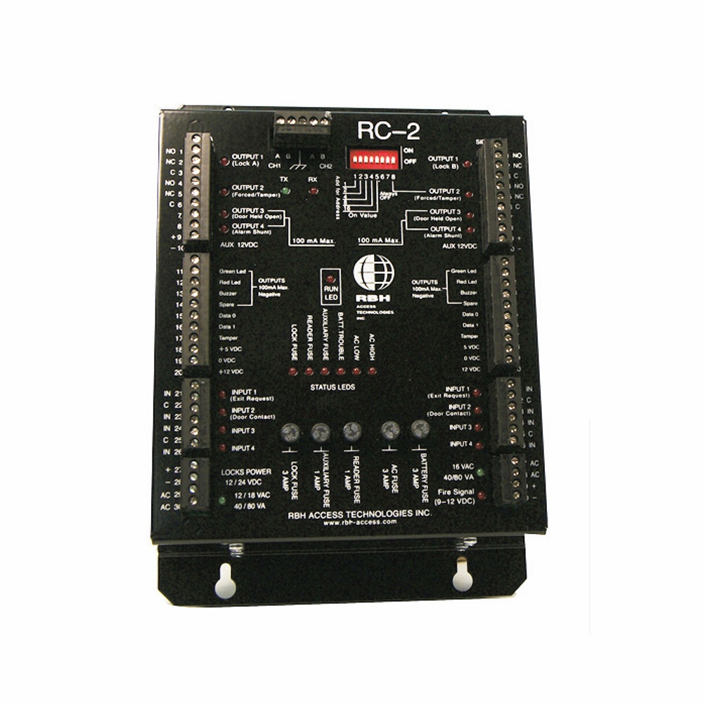
Reader Terminal - RC-2
- Reader Terminal
- For the management of 2 doors
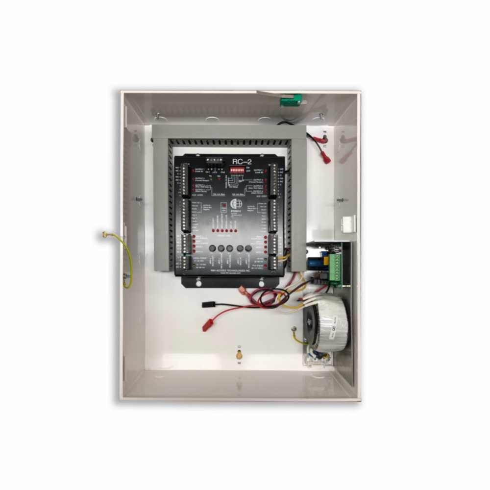
- Mounted in metal case with power supply
- 8 inputs and 8 outputs
- Built-in cabinet lamps
- Connects to the UNC-500 (/ NC-100) via RS485
- Multiple built-in regulated power supplies.
- Self-locked electrical lock, readers, aux, battery, and 230VAC failure, complete with fuse status and monitoring.
- Supports fully supervised RS485 communication.
- Dual RS485 ports designed to ensure data communications integrity in cases where a cable is shorted or cut over.
- Supports 8 independent multi-level monitoring inputs.
- All inputs are fully programmable and can be configured for one, two or no end-resistance monitoring. This allows to use an input at any security level.
- Supports two card readers of whichever technology: Proximity, Mag Stripe, Bar Code, Barium Ferrite, RF, Wiegand and Biometric Readers.
- Built-in lightning protection
- Plug in terminal connector on printed terminal connection diagram
- 26 on-board diagnostics LEDs
- Field Programmable I / Os
- Built-in fire alarm monitoring
- Powerful metal cabinet
- Power Supply: 1 x 16.5 VAC 40VA Transformer Terminal & Aux
- Door Lock Power: 1 x 12/18 VAC 80Va Transformer Max. 3 Amp.
- Voltage Consumption: 400 mA max. (Terminal)
- Battery Charger Output: Charging Voltage 13.8V Regulated Built-in Deep discharge protection and dynamic load test
- Recommended Backup Battery: 12V 7AH Lead Acid or Gel Cell
- Voltage Output
Reader 12V v / 1A (Fuse) 5V v / 1A (Fuse) Aux 12V v / 1A (Fuse) - Fuses (monitored): Battery 4 Amp.
- Reader 1 Amp. Auxilary 1 Amp.AC Voltage 3 Amp. Voltage 3 Amp.
- Reading connection: Supports 2 readers (Multiple formats)
- On-board reader tamper monitoringUndersteuning rød / grøn LED indikationUnderstødt Buzzer
- Cable Requirements: Type 20 -22 AWG6 or 8-wire, Displayed Distance: Max. 150 m
- Output: 4 x Form C relay, SPDT 2A @ 30VDC, dry contacts4 x Electronic drive (Max 100mA)
- Inputs: 8 x Fully monitored 1.2 or no EOL resistor (1K), 1 x Dedicated cabinet tamper Input1 x Dedicated fire alarm input Analog loop resistance measurement and reportingCable requirements Input: 20-22 AWG 2 Lead max. 300 m.
- Communication: Speed 38,400 bits / sec.D-Net Ports: 2 x Fully Monitored RS485 PortsKabling: Ring (Short / Open Circuit Protected) Cable Requirements D-NET Type: Shielded pair-twisted AWG 20-22Width: Max. 1000 m.
- On-Boad Dianostics Status LEDs: 8 x Output LED 8 x Input LED, 1 x Fire Stat. LED, Communication: 2 x RX, TX LED, 1 x RUN LED, Voltage: 4 x On / Off LED, Fuses: 4 x Status LED
- Dimensions: 25H x 18B x 10D in cm.
- Temperature: 0 - 70 ° C
- Humidity: 20 - 80% RH (Non-Condensing)
AxiomV Brochure (Eng).pdf (5.7 MB)
RC-2 • AxiomV - Datablad (DK).pdf (1.1 MB)
RC2 - Datablad (Eng).pdf (927.9 KB)
Print PDF

